Maschinenlabor
Test facilities
Test Facilities
- Overview
- Radial Fan
- Reciprocating compressor
- Turbo Compressor
- Francis/Pelton Turbine
- Kaplan Turbine
- Wind tunnel
- Pump
- Rotor dynamics
- CFD
Overview
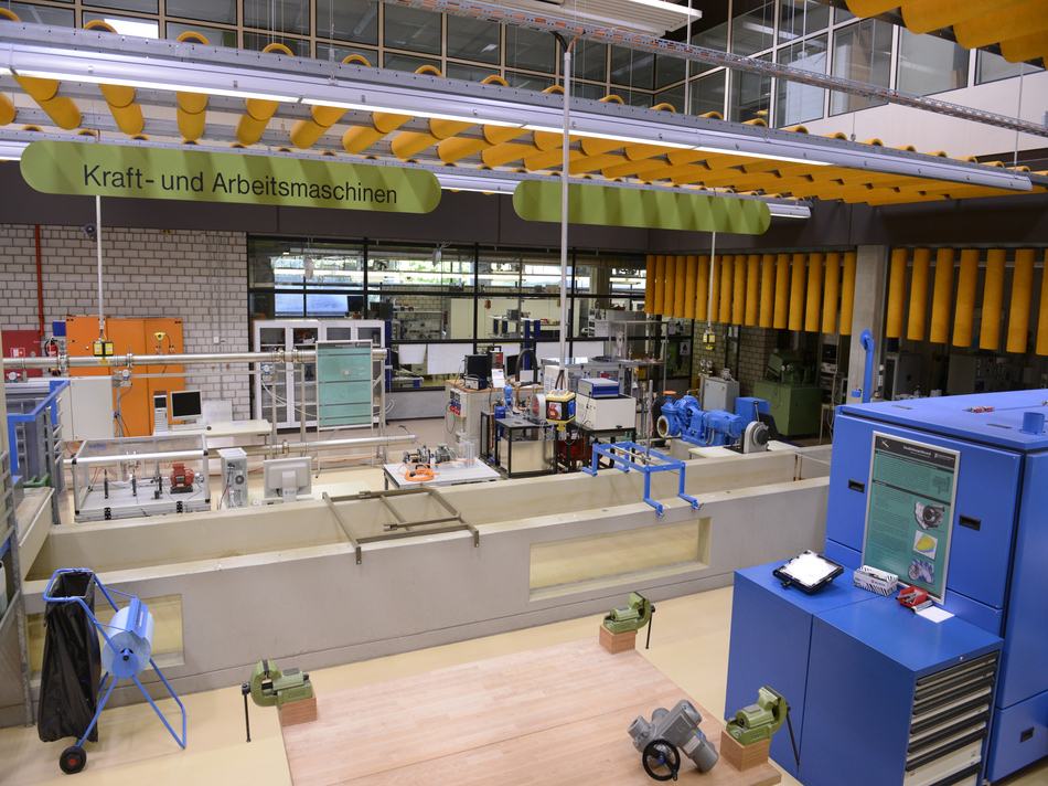
The test facilities in the laboratory allow the investigation of different fluid machines. Some of the test benches were created in-house and some were obtainen partly from external companies. The test benches are use for the laboratory lectures, in which students from different semesters operate the facilities themselvers and carry out measurements. In addition, the test stands are used for project work in teaching and research, especially in the context of students work.
Test bench Radial Fan
The test bench enables the measurement of a radial fan within a pipe system. Fans are turbo-machines for conveying gaseous media such as air, e.g. in living space ventilation and air conditioning. The most important types are radial and axial fans, while each name corresponds to the direction of air outflow. The selection of a fan and its performance range requires knowledge of the functionality, the fan characteristic and the system boundary conditions.
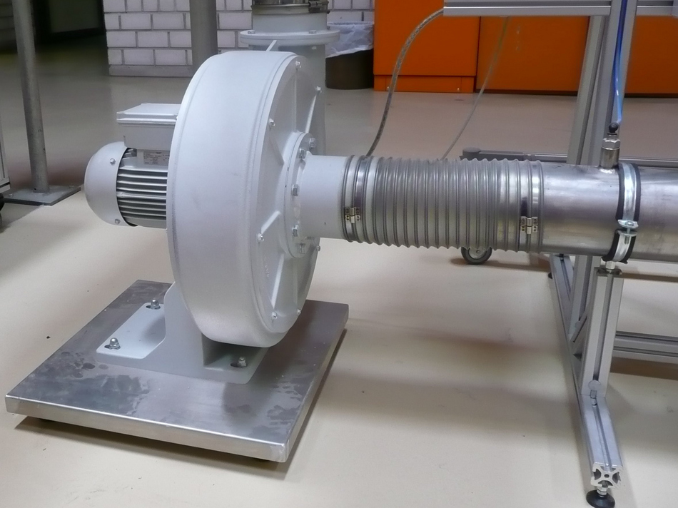
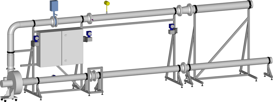
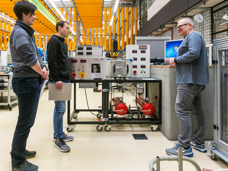
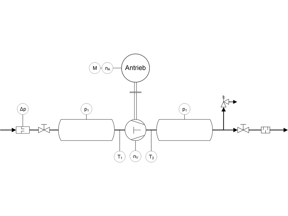
Test bench setup
The single-stage reciprocation compressor is driven by a drive unit via a belt. The sucked in air reaches the compressor via a suction container, a Venturi nozzle measures the volume flow rate. The compressed air is fed into a pressure vessel, the final pressure of which can be adjusted using a manual valve at the vessel outlet. Temperature sensors are attached to the compressor's suction and delivery connections, and manometers indicate the pressure in the two containers. The complete characteristic map of the compressor can be determined by varying the final pressure and the speed of the compressor.
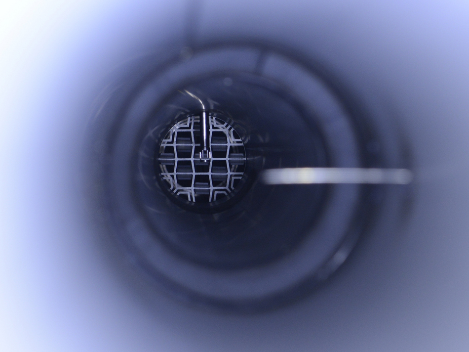
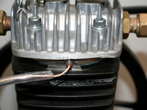
Extension indicator diagram
By installing additional sensors, it is also possible to record an indicator diagram on the test bench. An indicator diagram shows the course of pressure and volume in the working chamber during a working cycle and thus enables a clear representation of the processes in the compressor. In order to achieve this, a miniature pressure sensor was installed into the working chamber of the compressor and a rotary encoder for determining the working chamber volume was mounted on the pulley. The determination of indicator diagrams is an important development of the test bench and expands the possibilities for the experiments in the machine laboratory.

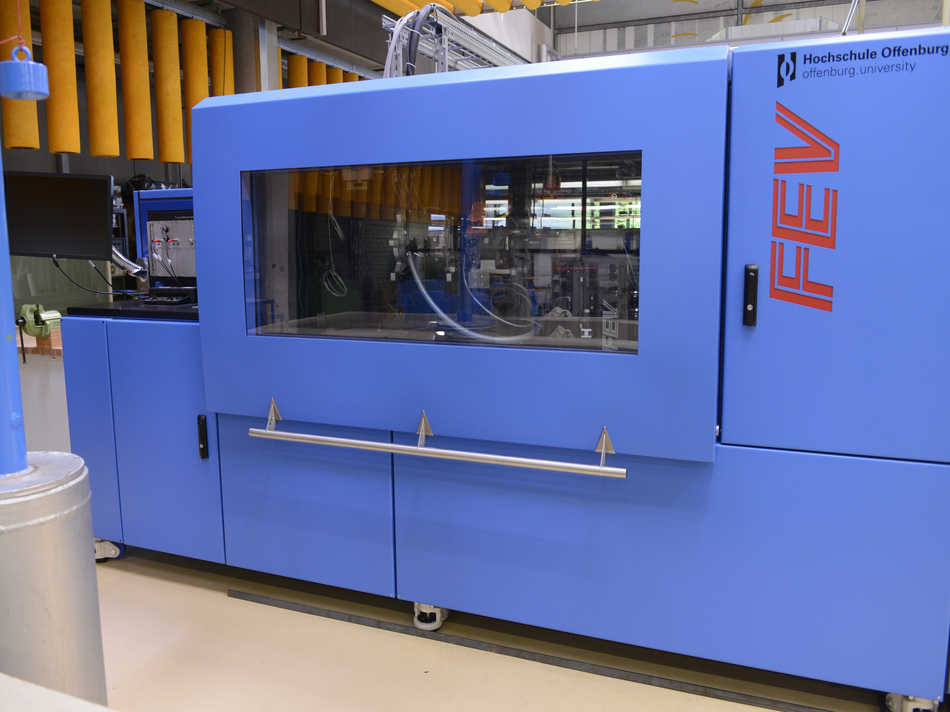
Test bench Turbo Compressor
The turbo compressor test bench at the Offenburg University of Applied Sciences is a special test stand for research and teaching. It is a one-off production in order to show teaching content and investigate phenomena from different disciplines, such as B. mechanics, thermodynamics and fluid dynamics. For teaching, this allows networked and interdisciplinary work using the example of a turbo machine operated at high speeds. In addition, the design of the test stand allows the investigation of compressors of different sizes, drive power, and also machine elements of high-speed machines such as bearings and spindles.
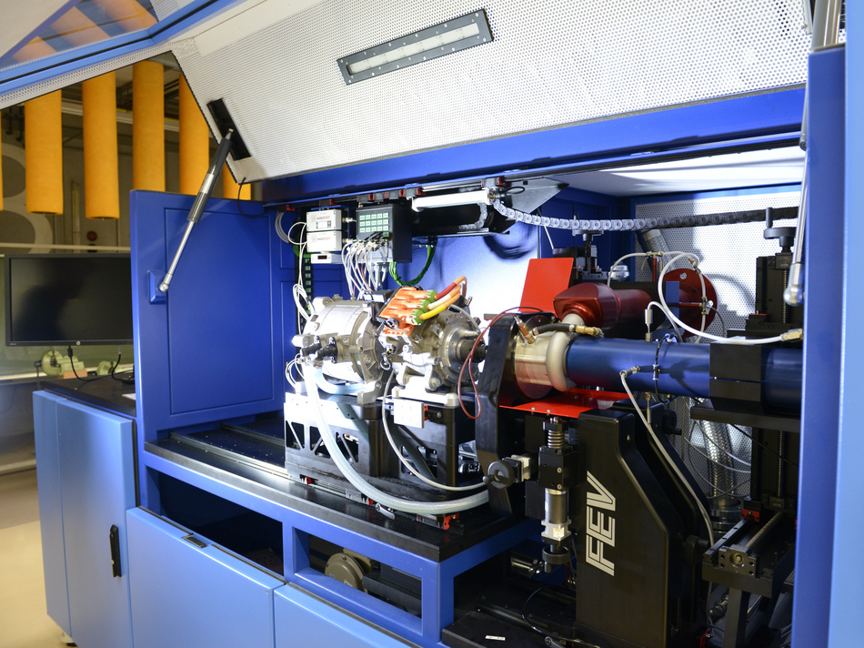
Test bench setup
Essential elements of the test bench concept are the flexible mechanical mounting of the test objects, which can be adjusted with high accuracy, the high-quality measurement data acquisition and the flexible test bench control, which also enables automated test cycles. The sensors include a rotary piston gas meter with a humidity sensor for volume flow measurement, several measuring points for temperature and pressure as well as sensors for measuring torque and speed.
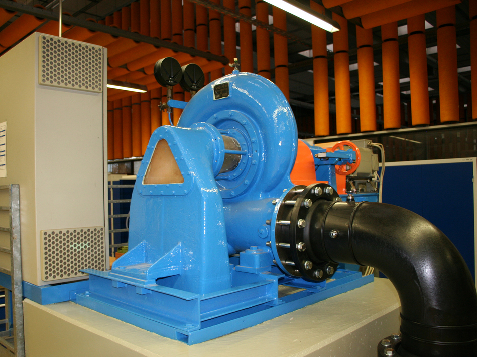
Test bench Francis/Pelton Turbine
The test bench is used to investigate constant and positive pressure turbines; a Pelton turbine and a Francis turbine are available for this purpose. Different height differences can be achieved by adjusting the pre-pressure while the turbine speed can also be varied. For example characteristic curves for different speeds with variation of the guide vane position (Francis turbine) or the needle valve position (Pelton turbine) can be created.
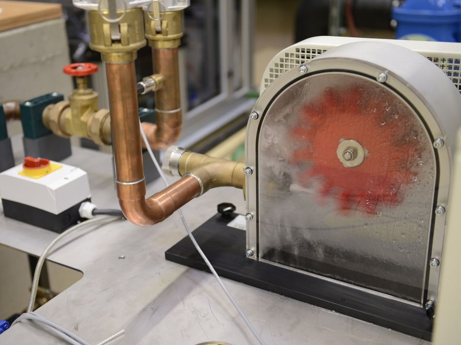
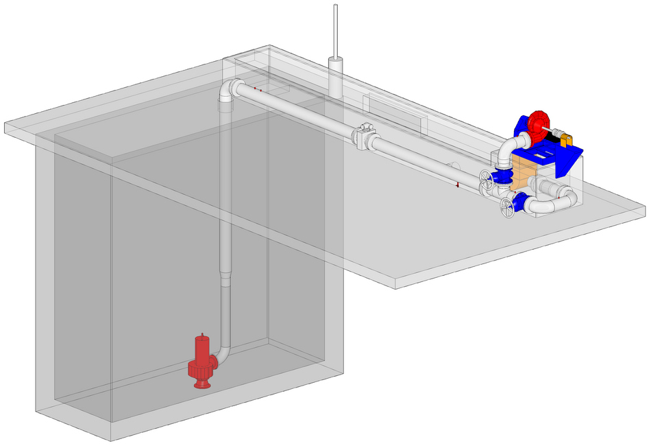
Test bench setup
The focus of the test bench is the respective turbine, which is connected to a brake unit via a belt. The supply takes place via a water tank, from which a speed-controlled circulation pump conveys the water to the turbine. In this section, volume flow rate, pressure and temperature are measured. After the turbine, the water is returned to the tank. On the Pelton turbine, the nozzle cross-section at the inlet can be changed using a needle valve; on the Francis turbine, the position of the guide vanes can be adjusted accordingly using a lever.
Test bench Kaplan Turbine
The Kaplan turbine is a so-called “high-speed” turbine with a high specific speed. It is used for large volume flow rates and low heads, i.e. for run-of-river power plants. In the lab, the operating behavior of a Kaplan turbine with a spiral casing can be investigated.
Test bench setup
A submersible pump supplies water from a underground tank via a pressure line through the turbine, from which it flows back into the basin through an open channel via an overflow weir. By changing the pump speed via a frequency converter, the pressure in front of the turbine can be varied and a variable head can be specified. The water reaches the turbine via a spiral casing and flows radially through a guide vane apparatus, whose blades are twistable via an adjusting ring. This changes the flow cross-section and the flow rate. The axial runner can be observed through the plexiglass suction tube, as well as an adjustment of the rotor blades. This adjustment is done by a tension rod. In addition to a magnetic-inductive sensor, the overflow weir in the water channel is used to determine the volume flow rate. For this purpose, the water level is measured using a mechanical sensor.
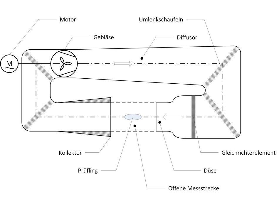
Wind tunnel
Wind tunnels are used for the aerodynamic investigation of (partial) objects such as aircraft or automobiles. The wind tunnel in the fluid machines laboratory fis used in the context of laboratory events, in which the flow around an wing profile is measured. In addition, the wind tunnel is used in projects, such as for components of the "Schluckspechts" - the energy-efficient vehicle of the Offenburg University.
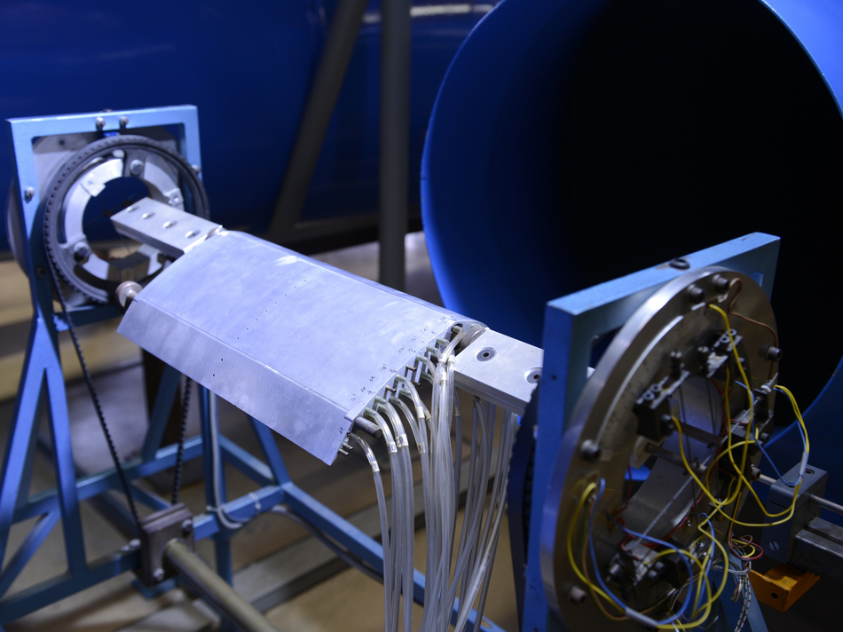
Test bench setup
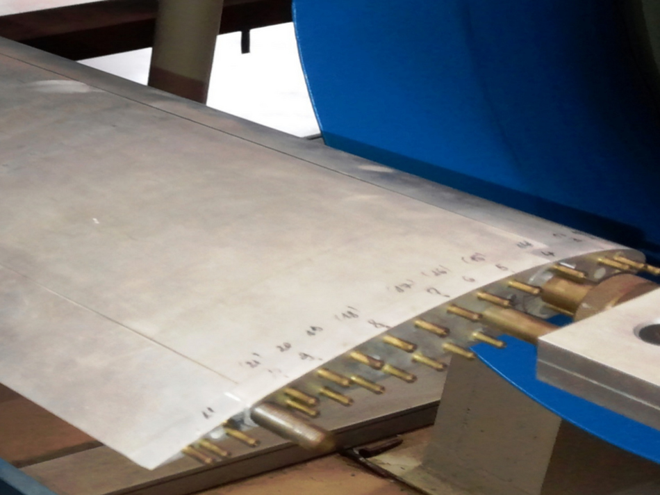
The wind tunnel of the Offenburg University is of the Göttingen type, i. H. the air circulates in a closed circuit. The measuring section is open so that the test object can be seen and accessed. The flow is maintained by a frequency-controlled fan. The flow rate is measured with a Prandtl tube and a Betz manometer. As part of the laboratory test, the pressure distribution on a wing profile is measured by means of a multiple U-tube manometer and the force is measured using bending beams with attached strain gauges.
Variable Pump test bench
Pumps are fluid machines that are used to convey liquids. Areas of application are e.g. the circulation within heating systems, the dosing of liquids and the emptying / filling of containers. Pumps exist in different types and sizes. To characterize the operating behavior of a pump, the pump curve is used, which shows the relationship between the delivered head and the flow rate. On the pump test bench, it is possible to measure such a characteristic curve.
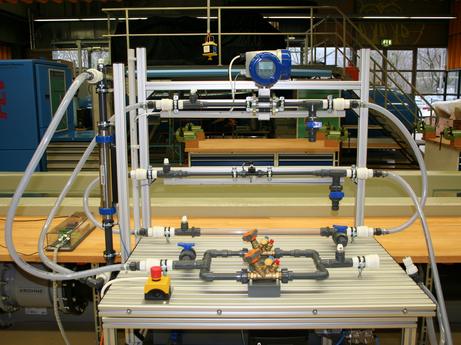
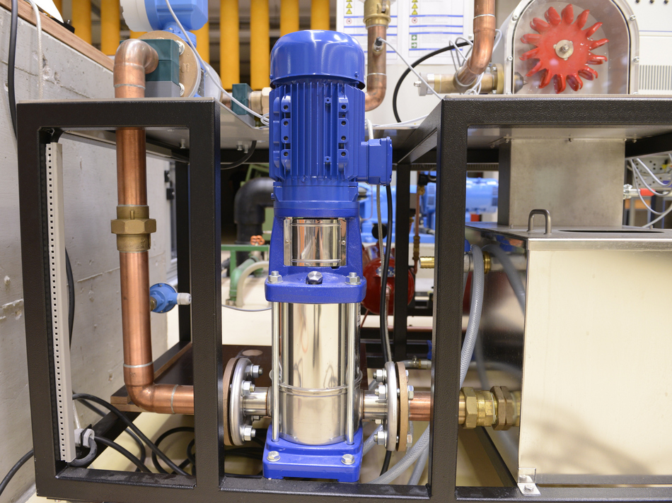
Test bench setup
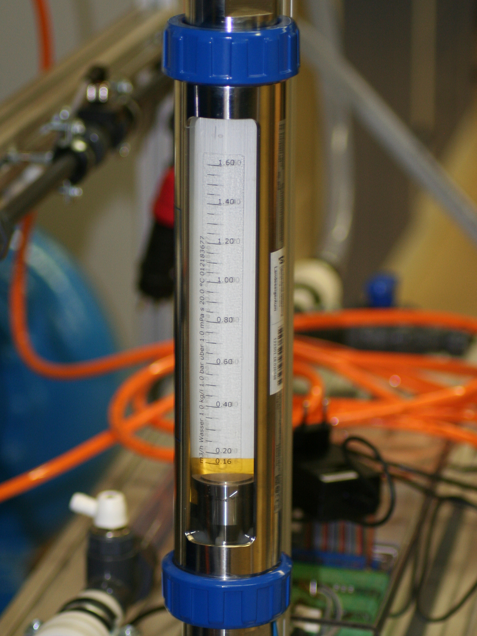
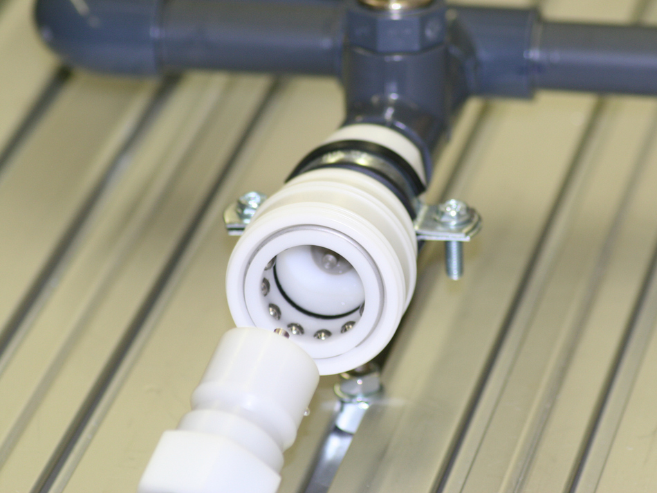
The center of the test stand is a three-stage centrifugal pump that is driven by a frequency-controlled motor. The pump is integrated in an assembly with connecting pieces for pressure measurement. Further hydraulic assemblies include a valve control, a water reservoir and various flow meters. Each of the assembly has two connections to which a hose can be linked using a plug connector. In this way, the assemblies can be connected in any way to form an overall system.
Variable operation of test bench
The test bench allows the adaption of the test to the requirements and the time available. The most comprehensive and time-consuming variant includes the definition of a measuring system and its hydraulic interconnection, the representation of the system in a piping and instrumention diagram, the electrical connection of the sensors to the data acquisition system, the necessary adjustments within LabVIEW and the execution of the experiment with subsequent evaluation. By providing individual steps in advance, the time and complexity of the experiment can be reduced.
Test bench Rotor dynamics
Turbo machines contain rotating shafts as an essential component, on which, among other things, the impeller is attached. Since the mass distribution in the rotor is not completely rotationally symmetrical, vibrations occur during operation. In the critical speed range, these are so large that they can destroy the component. In practice, care must therefore be taken to stay below the critical area or to drive through the critical area quickly. The test bench allow examing these dynamic problems using a simple, oscillating system - the Laval runner.
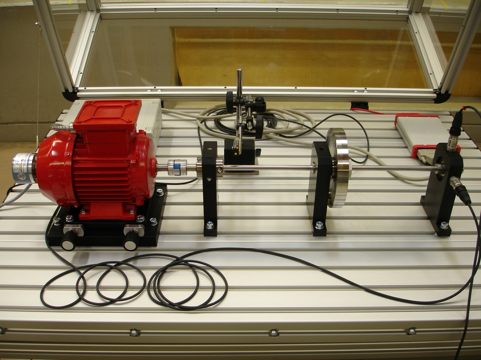
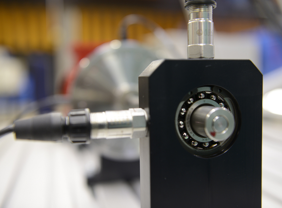
Test bench setup
Basically, the experimental setup consists of the three components drive unit, control unit and shaft. A speed-controlled asynchronous machine drives a shaft via an elastic claw coupling, which is attached to two bearing blocks by means of self-aligning ball bearings. A mass disk is mounted on the shaft, onto which a corresponding imbalance can be imposed using weights of different masses. Depending on the speed, the deflection of the shaft is recorded using acceleration sensors and displacement transducers. A safety bearing limits the wave movement in the near-resonance area to harmless deflections.
Computational Fluid Dynamics
Computational Fluid Dynamics is an important addition to the analytical and experimental fluid mechanics. With the help of numerical methods, the fluid flows and heat transfer from a wide variety of objects can be simulated. In the laboratory for fluid machines, models of flow machines are created as part of projects, the accuracy of which is checked by measurements on the respective test stands. The models are used to carry out analyzes of the machines and to develop and evaluate optimizations. Different commercial and open source simulation environments are used.